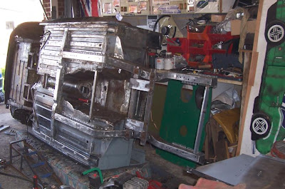
It is quite difficult, if you have never studied the structure of your body shell, to understand just how important the chassis rails are, as they carry most of the load from the front suspension, not to mention that the engine is mounted on them. I had to replace them, but it was not going to be easy as there was a very real risk of getting it slightly wrong and utterly wrecking the whole car, making the entire project so far a complete waste of time and money.
No pressure, then.
 This sort of thing was heppening everywhere- corrosion from the inside out, and the outside in, severely weakening what are really quite complex and important steel structures.
  I did some repairs to the worst area to give enough strength to allow me to use the spit earlier on in the restoration, but alreay alarm bells were ringing at the sight of this much rot.
 The inner wings which are fixed to the chassis rails also carry a lot of load, and these had been removed at the back for the replacement of the footwell ends. So all that was holding the chassis rails to the rest of the body shell were the tack welds along the floor pans and footwell ends, as well as the oil cooler tray and the support underneath it, which spaces them at the front. So how the hell to replace them without getting it wrong? Their alignment is paramount to not only the handling but the entire safety of the car. Food for thought was the fact that when the car was built, and indeed even when new body shells are put together by Heritage, they are just placed in jigs then twatted with a big hammer until they fit in the correct place. And the front cross member, which carries the steering and suspension and attaches to the chassis legs, is mounted on rubber pads. It’s not as precise as it all seems.
But this is no excuse not to get things perfect. It all needs to line up correctly, and it all needs to be in exactly the correct position. It there was even the slightest problem along the way, I know I would feel bad even when the car is finished and back on the road, I would not want to drive something distorted and dangerous.
I could not find any literature relating to the replacement of chassis legs. The only reference I have ever seen is in an article from “Enjoying MG” from several years ago, when during a restoration a chassis rail was found to have been bent and it was replaced be a specialist. But surely this has been done before, after all Heritage do make replacement chassis legs, but I wonder how many they have ever sold??
The logical thing to do was to replace one at a time. That way, I could go by the position of one original leg to space the new one correctly, then the second new one could be spaced by the position of the first. So I made some jigs to allow me to do just that.
Meet the jigs!
The first is a copy of the front cross member. I was considering using the cross member, stripped bare and bolted to the chassis rails. However, it still weighs a fair bit even when stripped, and this might have interfered with things. The second problem was that the bolt holes are oversize, and the protruding parts of the cross member mounting pads/bushes fill in the gap so the bolt fits correctly. And even with my new polyurethane bushes, it still did not seem precise enough for this level of things.
In a freak turn of events, the frame of Nigel’s old treadmill came to the rescue, with a vast amount of steel box section of various sizes, all heavy gauge and ideal for what I was doing. So a substitute for the cross member was made, with two long lengths of steel box with holes accurately drilled for the cross member bolts at each end, which were bolted tightly into place on the chassis legs, then two short pieces of box section were welded across them to space them correctly. Full throttle on the welder, plenty of heat and I had a lovely jig. This was removed, then refitted, then removed, and refitted quite a few times, to check it fitted perfectly, and also that when it was bolted up tight it would not try and rotated a new unsecured chassis rail in any way. It did not, and it was a tight and precise fit into place with the bolts. Ideal!
That held the chassis rails in position in the cross member area. At the front, a length of box section was bolted to the holes in the very ends of the chassis legs, to keep them spaced correctly. This would also held keep things in shape when I was replacing the oil cooler tray.
At the back, where the chassis rails run parallel to each other underneath the floor pans, two spacers kept them spaced. These were made from steel tube, also from the old treadmill, with a 90 degree angle section welded to each end, cut from a piece of large box section. This would keep the legs the correct distance apart, and were a nice snug fit.

A couple of these held things together further back, Again, very precise, even if it does not look it! The second got cut up as soon as it was no longer required, and became something else. I can't remember what though, so it can't be important or worthy of note and is not relevent to this, why do i bother so arghhh I'm just going to bail out of this pointless sentenc

Once of the spacers in place, the other went further back closer to the new crossmember. Note the piece of steel tube welded in to the front of the transmission tunnel to keep it correctly spaced. Probably unnecessery but I'm taking no chances. And the other piece of steel tube ensures no movement of the old chassis rail.
At the rear, a couple of small clips made again from box section fitted over the cross member and located the chassis rails laterally at the back. As it turned out, these were unnecessary, but you can’t be too careful with anything!
And that was enough to correctly space the new chassis rail from the other. Lines were scribed onto the floor pan to show the position of the old chassis rails, as a visual alignment check. The rest of the body shell was certainly adequately braced, it was stable on the mattress, I had plenty of grinder discs in stock…. I had run out excuses. Off with a chassis rail. The top one first, which was the offside.
The tack welds which held it to the floor pan and footwell end were ground down, then it was cut away from the oil cooler tray at the front, and the spot welds which held it to the oil cooler tray were drilled out. A bit more careful grinding, and it was off. What a relief that there was still a great deal of strength in the other chassis rail, I was a bit worried about it keeping in position once the other was separated from it, but it couldn’t have been better.
Then the cross member jig was bolted to the remaining chassis rail, and the new one lifted into place. The bolts were slotted in, and the two spacers quickly slotted in further back. The front spacer was bolted on, and hey-ho, it fitted perfectly inside the scribed lines all the way down, and it was in exactly the right position. So it was quickly tacked into place, then every other plug-welding hole in the chassis leg was extended through the floor pan, so the two could be temporarily tightly bolted together while the surrounding area was seam welded. This of course was done a little at a time, to avoid heat distortion and burning of my nice zinc primer which had replaced the Heritage paint at either end of the box section (the central area of the chassis rail is box section, so I left the Heritage paint alone as there was no way I could effectively strip it then repaint it). The holes were then filled in with weld, to act like a plug weld. All was well, so the rear of the chassis rail was welded to the cross member, one down, one to go!
The bottom chassis rail (nearside) had the tack welds ground away, then it was unbolted from the cross member and front jig. It fell away with the oil cooler tray support (to be re-used) and the remains of the oil cooler tray (to join the big scrap pile). The new chassis rail was lifted into its place (after cleaning up of the remains of the tack welds and the floor pan had been painted with weld-through primer in that area, of course) and bolted to the other chassis rail via the jig. Of joy, it all lined up, and it was in the same place as the original chassis rails. So it got the same welding treatment, which has turned out to be incredibly strong, as required. And that was that. The chassis rails done. The cross member jig could be removed and replaced with the same precise fit that it had with the original chassis rails. The rear spacers could be fitted and replaced with the same snug fit as before. The front spacer was temporarily welded between the chassis legs, to hold things steady while I fitted the new oil cooler tray.

Hey hey HEY! Look at that! Two new chassis rails, without and movement or damage! It looks flimsy at the front at the moment, but it is not by any means.

I did all of this, apart from the transmission tunnel. And it's all kept in the correct shape. Woooo-Yeah! Lots of mmmmmmmmmmmmmmmmm groovy new steel!
What a relief, I had not ruined my little car, and I feel a great deal happier now those nasty old chassis legs have been replaced by clean fresh steel, which will be adequately protected inside and out. It just goes to show, with careful planning and a lot of care, most things are possible, even if people scoff at you when you order your new chassis rails. Surely that’s the most difficult part of the restoration over….?


No comments:
Post a Comment